
Introduction
Several things to change on the original post:
- The controller needs to change (GRBL not satisfying)
- The emergency stop button needs to be decoupled from the controller
- Add a flow sensor for the pump and cut the laser in case of failure
- Add a cooling water temperature sensor and shut off the laser in case of overheating
- Put the lid switch directly on the laser cutter
This article will highlight the different elements, explain what their purpose is and how I integrate them in this project. You will have access to the technical documentation and diagrams at the end.
The controller
Presentation
It’s literally the brain of the machine and it has to be reliable and accurate. Arduino works, but GRBL does not allow a meaningful interpretation of the GCODE and the overall performance of the machine (acceleration, accuracy) is not very good. Not to mention that the driving part of the motor is delegated and becomes a big black box (proprietary components and low quality). The research I made led me to choose SmoothieBoard. I contacted RobotSeed, I explained the project and they offered me to perform my tests on a 3X 1.0 which contains 3 engine drivers and 2 MOSFET low intensity (5A / 24V max).
I took you the best picture I could for you to see the details, connectors and other things.

Elements to be considered
More possibilities
This board has been designed to support laser cutting from A to Z, so it interfaces much more finely with the laser driver than the Arduino would.
“raster” mode
This version of SmoothieBoard (do not hesitate to regularly check their KickStarter page!) Does not have an ethernet port and I could not put my files on the SD card because the controller will be locked inside the machine. So I’m going to have a problem if I want to use “raster mode” for engraving (indeed, it takes a communication speed between the GCODE provider and the control card higher than the speed of execution … complicated by USB!). I do not intend to make engraving with this machine, but to maintain versatility. I will study the possibility to engrave in “vector mode” (everything will be explained on time). This would allow to have a machine that makes cutting while being able to put a small logo, a small inscription or other, without any problem.
Security
IMPORTANT
I will do my best to remind you how important it is to stay alive (and in one piece) when making and using the machine of this project. The assembly will make you handle tens of thousands of volts and a powerful laser that can cut 12mm plywood (and you will find without too much difficulty that you are more fragile than 12mm plywood).
The machine must be used as safely as possible : impossibility to access the laser when it is on, emergency stop, locking the machine by key, protective panels, cover that absorbs the wavelength of the CO2 laser .
Emergency stop button
The role of this button is to be able to disconnect the entire electrical network immediately, with a simple pressure (and therefore without going through a computer / controller or other logic board). Once the button is pressed it will be impossible to re-arm the machine without turning it and lifting it. I will add the need to have a key for more security (imagine an emergency stop following a dangerous manipulation, the user restarts and starts again to find a way around … it is better to report the incident to the technician who will take care of the problem before doing a reboot).
Cooling system
This is an undeveloped aspect in the original post and yet it is very important. The CO2 tube will heat and it must be cooled effectively to avoid damage (or worse). Normally it is a separate unit of the cutting machine (probably not to have water near the very high voltage). But in this project, everything is integrated and the exhaust ventilation is recycled to cool the water, which in turn cools the tube.
I wanted to install two security elements on the cooler:
- a water flow sensor that prevents the laser from starting if the pump does not supply the flow
- a temperature sensor that will prevent the laser from starting if the water temperature exceeds a certain value (to be defined later)
The lid
It’s simple: we open it, the laser stops. Immediately, without calculations, without waiting for the control board to give its opinion. A simple switch that opens the circuit to turn off the laser.
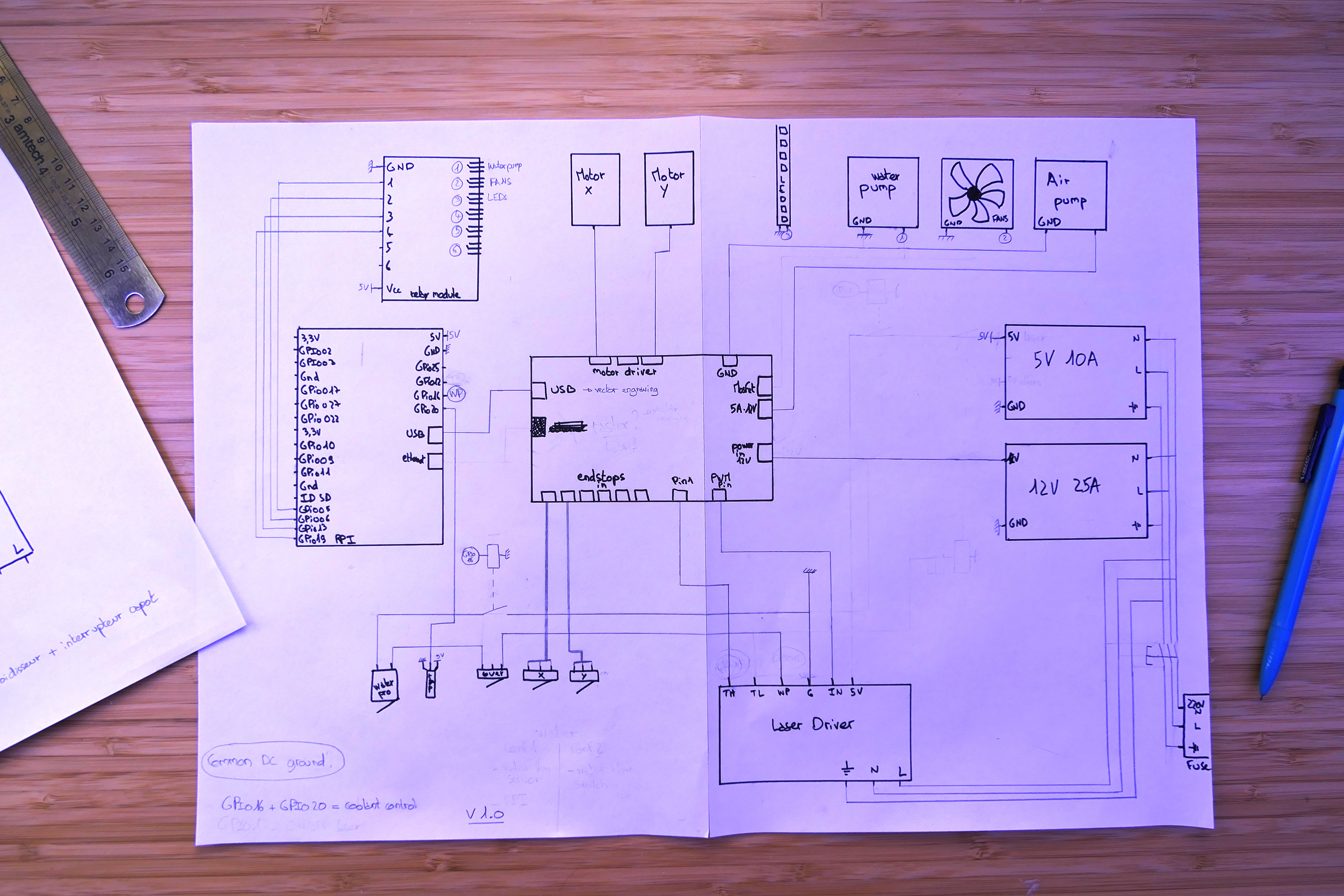
The diagram

So yes, it’s drawn by hand … but I will have lost too much time to find what OpenSource software to use and how to use it (already that the project asks me to learn a lot of things). Not really knowing the specific notation in electronics, I will detail the diagram:


- The connectors of the Raspberry Pi (RPI) are GPIO with number. If you see in the diagram a bubble “GPIOx” is that it is connected to the RPI. The RPI serves as the chiller’s brain and manages the ventilation, light and transfer from GCODE to SmoothieBoard
- Here is a relay panel to turn on / off the light, the ventilation, the water pump, and this since the RPI
- Connectivity is simplified for SmoothieBoard as it contains the drivers of the motors! Just connect the motors and the stop sensors to the corresponding pins (the laser driver will be detailed below)
- The 12V and 5V power supplies are connected to a fuse terminal block in case your home network has a problem. The connection of the cable is standard and you will make the machine in all countries 220V!
- The laser driver has its own schema based on the previous project, the manufacturer’s specification sheet and RobotSeed’s advice.
- TH is connected to a pin of the SmoothieBoard which will allow it to turn on / off the laser
- TL is not connected to anything (do not connect to the ground! Leave in the air)
- WP is connected to the ground (G) and I added two switches: the switch of the lid to cut the laser, the relay relay controlled by the RPI which will act as cooler (and which will cut if anomaly)
- G is connected to the logical mass
- IN is connected to the SmoothieBoard PWM pin that will control the power of the laser
- 5V is not connected to anything (not useful in this laser configuration)
- Ground, neutral and phase are connected to the terminal block with fuse
Use documents
Here are all the documents that allowed me to build the diagram. In case you want to make a different version.
Conclusion
The construction of the diagram allowed me to highlight the lack of fans in the original BOM (I added them to the first post. They will be bigger, more powerful and of course the DXF will be updated accordingly.
The integration of security features has been tricky due to an entry-level laser driver with a rather confusing specification sheet.
Now I can move on the other points. And if you ever have a remark, a question or something, do not hesitate to react in the comments or to contact me by email.
All the articles regarding this series are here : DIY Lasercutter
Leave a Reply