
Introduction
The original post is full of errors (junction in excess, junction missing, bad measurement, permutation of units and tens …). And the plan is quite difficult to read … So it took a lot of work and I progressed carefully not to end up with more profiles to buy.
I will try to include additional information to compensate for the errors. And I invite you to use this guide instead of the other …
Cutting

Security
It is important to stay alive and in one piece. Cutting aluminium profiles requires a circular saw with a metal blade. It is a tool that is dangerous for several reasons: it produces harmful dust, it projects shards, it is very noisy and it cuts.
I can only ask you to wear a mask, goggles, ear protection and gloves when you cut the profiles. Safety first !

The cutting
I use cutting oil to facilitate the work of the circular saw and preserve its blade. But as it is aluminium, just go slowly and everything is gonna be fine.
Regarding the cut line, I put it to the exact edge and cut it so that the blade removes the material downstream.


Then I try to number everything respecting the cut file of the original post. And as there are errors, I tried to number so that each section of 1980mm has the right number of sections without exceeding the length of the profile like it was before …


Here is the new cutting plan. I advise to indicate on the profiles their number and their length to find them back more easily (and it will enable you to better follow the pictures).

As you can see, I highlighted profiles that need to be cut off. The total length comes from an automatic calculation, so I am sure it matches.
For the next series of photos, I tried to properly indicate the corresponding numbers and lengths for you (if it’s too small, you right click on the photo, you open it in a new tab and you remove from the URL the WP resizing, I put pics in 4K normally …).


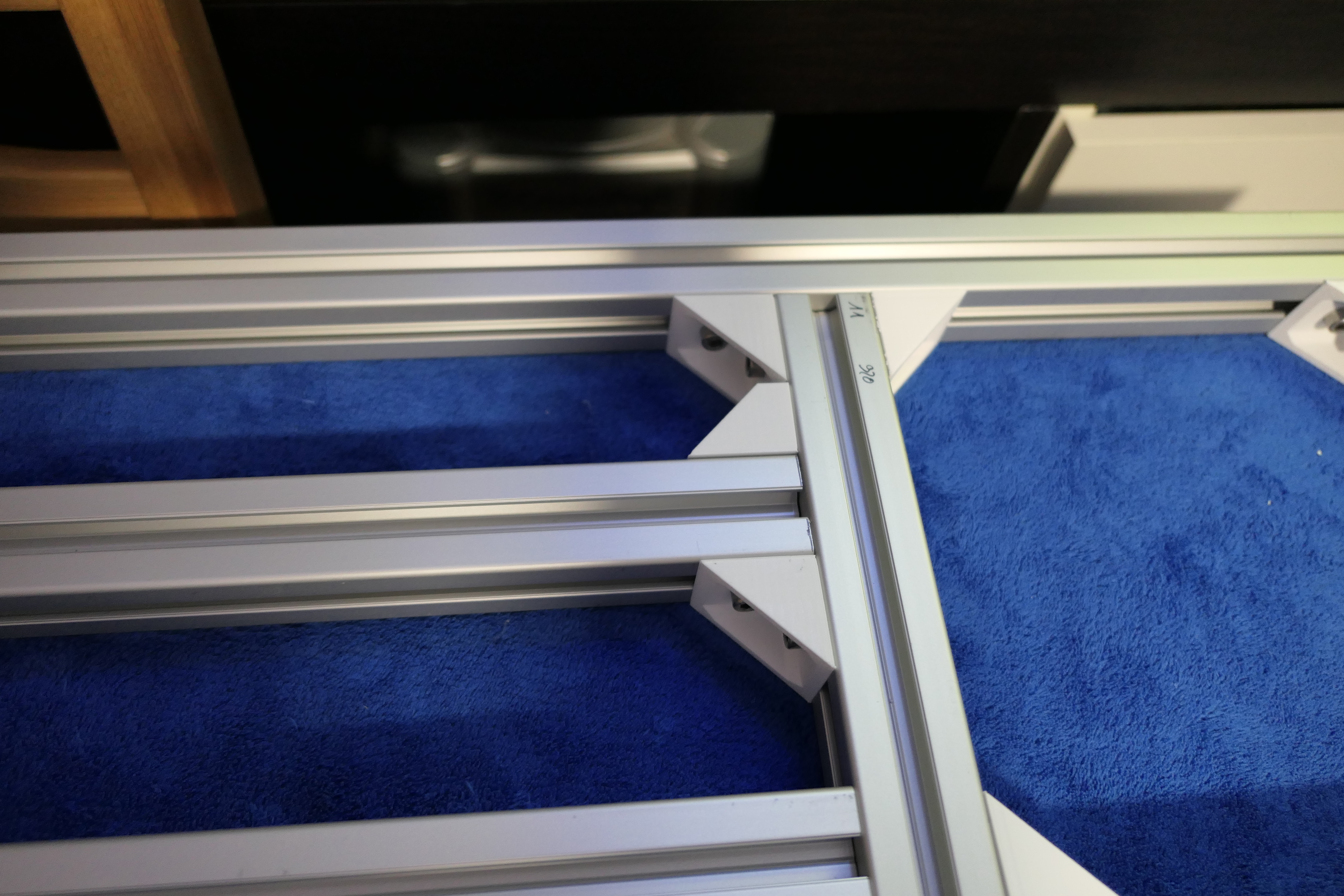
In order to mount the chassis, I had to redesign several parts. The printing was done with the following parameters:
- Material : PLA
- Nozzle : 0.4mm
- Infill : gyroid
- Infill : 40%
- Perimeters : 3
- Solid top and bottom layers : 5
- Layer height : 0.2mm
And the quantities are as following :
- 148 Corners
- 26 Short corners
- 14 Angled corners
- 28 Plates
- 3 Hinge shafts
Conclusion
Because of all the changes I had to make and the pieces I’m still waiting to receive, the making process is currently slow … However it allows me to build my own version of the laser cutting as I go up with this. It will have better parts, a better design, etc … This will allow me to offer you kits ready to mount – with instructions – on my shop (a bit like OpenBuilds).
Building and improving this project allows me to understand exactly how this machine works, even though there is a lot of frustration with each discovery of an initial design concern …
The next article will deal with the arrangement of internal mechanical parts, as well as electronics (I am waiting to receive some pulleys and to get some wood). I could also install the compression springs.
As always, do not hesitate to contact me if necessary !
All the articles regarding this series are here : DIY Lasercutter
Leave a Reply